Troubleshooting competition

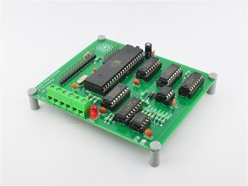
The PCB that we designed

Every year the department of electronics engineering at SPIT organizes an electronics hardware and simulation competition for the 3rd year students. This year I was a part of the organizing team and in charge of the hardware aspects of the competition.

There were three phases to this competition

  1. A quiz based on basic electronics concepts
  2. Students debug a circuit in simulation
  3. Students debug the same circuit in hardware

This year was a step up from the previous years as we involved the entire third-year class in the final phase that is the hardware phase.

Adithiya and I designed the PCBs and had 30 of them manufactured.

Due to some circumstanceswe got the PCBs very late and were hard pressed for time to have them assembled and tested. With the help of our classmates, we were able to solder all the 28 boards in one day!

Then began the task of verifying that all the boards were functioning as expected. Here we faced a lot of issues regarding noise induced in the power rails due to the digital logic ICs. This took us some time to figure out which was solved by adding filtering capacitors at the appropriate places in the circuit.

Due to various issues, we had to major problems with the procurement of the 8051 ICs. We learnt the importance of planning in the procurement of the components.

In the end, we managed to overcome all the issues and the competition was a success.

Here are some of the photos.

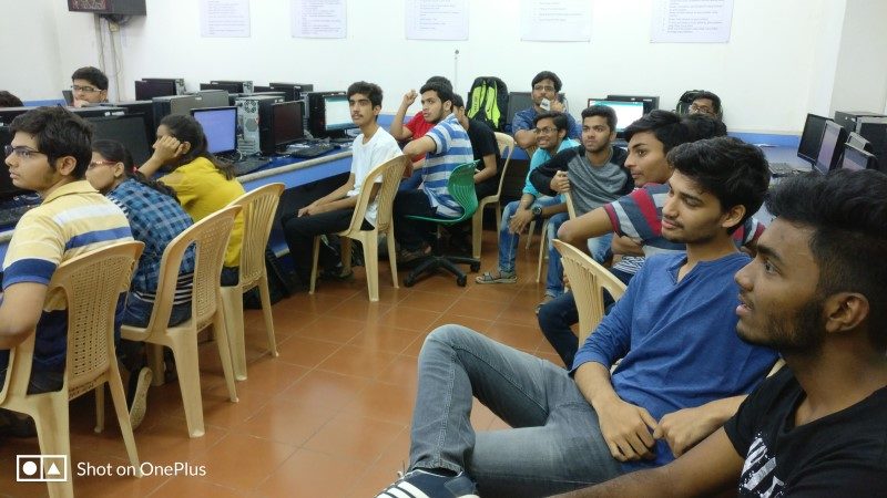
Team
Blank PCBs
Components
Assembly 1
Assembly 2
All assembled boards
2
The Team

Workshop on Introduction to Embedded Systems Design

1_01 (800 x 450)
IMG_20180321_190214802
IMG_20180321_234136578
IMG_20180323_144028923
IMG_20180324_140450
IMG_20180323_192221
IMG_20180324_140114433
The final board

You can view the detailed plan of our workshop here

After our last workshop on “Introduction to Microcontrollers, Sensors and Arduino“, we wanted to go further by taking a workshop on embedded systems. In March 2018, we (Srijal and myself) in collaboration with Electronics Students Association and IR cell of our college we conducted another hands-on workshop on introduction to embedded systems design.

The aim was to demonstrate the complete end to end process of designing and building an embedded system from scratch; right from hardware design, board assembly, board configuration and then writing the respective embedded C code to get the experiments to life without using any Arduino libraries.

For this purpose, I designed a custom board using the ATmega328p microcontroller. The board had an onboard LCD display, 3.3V & 5V regulators, ISP as well as serial programming interfaces.

The ATmega board documentation can be viewed here.
The example codes for both embedded C and Arduino can be found here.

We started the workshop with concepts of PCB designing and manufacturing. We went through the design process and the design considerations for the board.

On the second day, the participants completed the assembly of their boards by soldering through hole and SMD components. Along the way, we showed them tips and tricks of soldering. After testing all the boards, we had LED and LCD interfacing experiments. We ended the day with an example of ADC (Analog to Digital Converter) interfacing using a potentiometer.

Workshop on Introduction to Microcontrollers, Sensors and Arduino

Some of the photos from the workshop

You can see our detailed plan here.

The IEEE Student branch at our college invited Srijal and me to conduct a workshop on Arduino for the first year students. We decided to conduct an 8 hours workshop spanning over two days.

Our aim was to make the workshop completely hands on one and explain the theory through practicals. We did this because it is our firm belief that no concept can be understood by reading/listening alone; the only way to understand anything completely is by practically doing things and experiencing it. We wanted to start from scratch so that their base/foundation becomes strong and thus give them a platform to build their knowledge.

The first step for the hands-on workshop was to give them their own kits. For this, we assembled a kit containing all the required components.

Kit assembly

We started the workshop with simple examples such as blinking an LED, PWM (pulse-width modulation) then slowly moved up-to interfacing buttons, potentiometers, transistors, motors and ended the workshop with interfacing an ultrasonic distance sensor.

We first explained the concepts, circuit diagram and code to everyone and then using the kits they wrote the code and executed the project on their own.

Along the way, we showed them our projects to make them understand the application of what they were learning. This gave them a practical application understanding of the concepts that they had learned.

Feedback from all the participants

Some of the feedback from participants

It was funny how he articulated technology, didn’t bore us at all!

Excellent workshop and hats off to the hardwork done by Srijal and Chirag

We would like to enroll for future workshops as our practical knowledge is weak… I want more workshops

Liked the fact that we were given a lot of practical experience

It really motivated me to make projects myself

Journey of PCB designing

DSC_0642 (800 x 600)
DSC_0648
DSC_0624
DSC_0591
1 (4)
IMG_20180408_190752 (800 x 600)
1_01 (800 x 600)
rtrois
Troubleshooting (800 x 600)
Fixed DC supply

All my PCBs

I’ve designed PCBs for projects like the constant current load, real-time room occupancy system, PCBs to solve my own needs like making ac-dc power supplies, microcontroller boards etc. For conducting a workshop at my college; I designed an ATmega microcontroller board.

It all started with the RoboCon PCB designing workshop in my first year of engineering. We designed a blinky board which blinked 2 LEDs in sequence. It gave me a basic idea of PCB designing and I was on my way to designing more complex PCB’s.

Using this newly learned technique I went on to design and build my own DC power supplies which I still use to this day.

Next, I designed a micro-controller board very similar to an Arduino. I did this as it was more cost effective and I’d have another board that I could use in my projects.

Next, I designed the constant current load board which would be the most challenging design to date. The PCB was too complex and impractical to build by hand so I decided it was worth to get it professionally manufactured. I designed the board in Eagle and got it manufactured from PCBway (PCB prototyping company based out of China).

Constant Current Load

Next, I designed the ATmega board for the “Introduction to Embedded Systems Design, Embedded C Programming, PCB Designing and Soldering” workshop that we conducted in college. We assembled and distributed 10 boards for the workshop.

The last board that I have designed so far is for the real-time room occupancy system. It is the smallest board I have ever designed with the most component density. I have used small SMD packages like TQFP and SOT which have a very small lead spacing are quite challenging to solder by hand.

Breadboard2
1 (52)
1 (53)
1 (20)
1 (15)
1 (2)
Website3
Website2
Prototype on breadboards

Room Occupancy Sensor

Needless to say, I still have a lot to learn in the domain of PCB designing and I am only just getting started and the journey has been satisfying so far…..